
Direct-to-Chip Liquid Cooling: Working Principle, Architecture and Engineering Guide
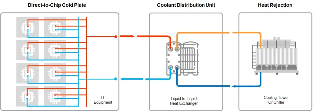
Direct-to-chip liquid cooling (also called D2C or cold-plate liquid cooling) removes heat from high-power processors by circulating coolant through cold plates mounted directly on the chip packages. It targets CPUs, GPUs, accelerators, and selected other components rather than cooling the entire server volume or relying primarily on air.
This approach has become the practical baseline for racks exceeding roughly 40–60 kW, particularly AI training and HPC nodes where individual chips routinely exceed 700–1000 W. It sits between conventional air cooling and full immersion: liquid reaches the primary heat sources while residual heat from memory, power delivery, storage, and networking still typically requires some airflow.
See ATTOM’s Liquid Cooling for Data Centers guide →
What Direct-to-Chip Liquid Cooling Is (and Is Not)
Direct-to-chip cooling uses conduction across a thermal interface material into a metal cold plate that contains internal flow channels. Coolant absorbs the heat and carries it out of the server through hoses and manifolds to a Coolant Distribution Unit (CDU). The CDU transfers that heat to a facility primary loop (chilled water, dry cooler, or free-cooling system).
It is not immersion cooling. Coolant does not contact the electronics or submerge the server. It is also not a rear-door heat exchanger (RDHx), which cools exhaust air after it leaves the servers. Direct-to-chip is a hybrid system in most deployments: the majority of heat (often 70–90 %) is captured at the chips, while the remainder is handled by residual air cooling.
The technology is defined by the location of heat capture (chip surface), the closed secondary loop, and the separation between the technology cooling system (TCS) and the facility water system (FWS).
How Direct-to-Chip Liquid Cooling Works
A cold plate is clamped onto the integrated heat spreader of each high-power component. Thermal interface material fills microscopic gaps so heat conducts into the plate. Coolant enters through an inlet, flows through microchannels or optimized internal geometry, rises in temperature, and exits through an outlet.
The heated coolant travels via flexible hoses and quick-disconnect fittings to rack-level supply and return manifolds. From the manifolds it reaches the CDU. Inside the CDU a heat exchanger rejects the heat to the primary facility loop while pumps maintain flow, pressure, and filtration. Cooled liquid returns to the servers.
Most production systems operate in single-phase mode: the coolant remains liquid throughout the secondary loop. Heat is absorbed as a temperature rise. Flow rates, approach temperatures, and pressure drop are sized so that chip junction temperatures stay within the processor’s specification under sustained load.
The secondary loop is isolated from the facility water. Typical secondary fluids are water-glycol mixtures (often propylene glycol 25 % or similar) chosen for freeze protection, corrosion inhibition, and biological control. Filtration (commonly 50 µm on the secondary side) protects the fine channels inside cold plates.
Main Components
- Cold plates — copper or copper-alloy blocks with internal channels matched to specific processor packages. Thermal resistance of the plate plus TIM is a primary performance driver.
- Thermal interface material — the critical interface layer; voids or excessive thickness raise thermal resistance significantly.
- Server-level tubing and quick-disconnects — self-sealing, dripless fittings that allow server insertion and removal without draining the loop.
- Rack manifolds — stainless-steel supply and return headers that distribute coolant to multiple servers and balance flow.
- Coolant Distribution Unit (CDU) — the hydraulic and thermal bridge. It provides pumping, heat exchange, filtration, expansion volume, leak detection, and monitoring. CDUs are available in rack-mount, row, and sidecar form factors, and in liquid-to-liquid or liquid-to-air configurations.
- Coolant chemistry and filtration — maintained to prevent corrosion, fouling, and biological growth inside the microchannels.
- Monitoring and controls — temperature, pressure, flow, and leak sensors tied into the facility BMS or EMS, commonly via Modbus or SNMP.
Single-Phase and Two-Phase Approaches
Single-phase systems keep the coolant liquid. They dominate current deployments because behavior is predictable, pressure requirements are moderate, and integration with existing facility water is straightforward. Heat removal capacity scales with mass flow rate and allowable temperature rise.
Two-phase systems allow the coolant to boil inside or near the cold plate, absorbing latent heat. They can handle higher heat flux at lower flow rates, but introduce pressure management, vapor handling, condenser design, and more complex fluid charge control. Two-phase direct-to-chip remains less common outside specialized high-flux applications.
The choice is driven by heat-flux density, operational tolerance for complexity, and long-term fluid management rather than a simple “more advanced” ranking.
System Architecture Layers
A typical installation is organized in three layers:
- Server layer — cold plates, TIM, internal tubing, and quick-disconnects.
- Rack layer — manifolds, hose drops, leak detection, and optional in-rack monitoring.
- Facility layer — CDUs, primary piping, heat rejection (chillers, dry coolers, cooling towers, or free-cooling systems), and building controls.
This separation allows the secondary loop to run at higher temperatures (often 30–45 °C supply) while the primary loop remains compatible with existing plant water. Higher secondary temperatures expand free-cooling hours in many climates.
Applications in High-Density and AI Environments
Direct-to-chip cooling supports GPU and accelerator servers whose thermal design power exceeds the practical limits of air cooling inside a standard chassis. It is used in AI training clusters, inference farms, HPC systems, and any deployment where rack density moves past 40–60 kW and continues toward 100–150 kW or higher.
Because the servers remain largely standard form-factor machines with added cold-plate plumbing, the technology is suitable for both new builds and phased retrofits. Liquid-to-air CDUs (sidecar style) further reduce dependence on facility chilled water, which is useful in brownfield sites.
Residual air cooling is still required for non-cold-plated components. Operators therefore retain some airflow infrastructure, although fan power and overall cooling energy drop substantially compared with pure air systems.
Comparison with Other Cooling Methods
Air cooling remains simplest for lower densities but hits practical limits as chip power and rack density rise; it also consumes more energy for fans and compressors.
Rear-door heat exchangers capture heat from server exhaust air. They require less server modification and are easier to retrofit, yet their capacity is typically lower (often 30–80 kW class) and they still leave the room air system handling a larger share of the load.
Immersion cooling submerges entire servers in dielectric fluid and can reach higher densities with near-100 % heat capture. It demands greater changes to server design, service procedures, structural loading, and fluid handling. Capital cost and operational unfamiliarity are higher.
Direct-to-chip occupies the middle ground: higher performance and efficiency than air or RDHx for dense AI loads, with lower disruption and lower cost than immersion for most enterprise and colo environments.
Engineering Considerations and Constraints
Leak management is non-negotiable. Dripless quick-disconnects, secondary containment, continuous leak detection, and response procedures are standard requirements.
Flow balancing across many cold plates matters. Uneven distribution produces hot spots. Manifold design, orifice sizing, and pump control must keep every plate within its design flow window.
Coolant quality control is continuous work. pH, inhibitors, particulates, and biological activity must be monitored; microchannel fouling is difficult to reverse.
Hybrid nature means residual heat still needs air handling. Fully liquid facilities are rare; most sites run mixed environments and must size both systems accordingly.
Material compatibility across cold plates, hoses, fittings, CDU components, and facility piping must be verified. Mixed metals and incorrect elastomers create corrosion or permeation risks.
Power and control redundancy for the CDUs is required. Loss of secondary flow can force rapid thermal throttling or shutdown of high-power chips.
Standardization of fittings, cold-plate interfaces, and fluid chemistry is still evolving. Multi-vendor environments need careful interface specifications.
Staff training and procedures for fluid handling, server swaps, and emergency response differ from pure air-cooled operations.
Selection Criteria
Evaluate the actual heat flux and rack density first. Below roughly 30–40 kW, air or RDHx may still be sufficient. Above that threshold, quantify the percentage of heat that must be removed at the chip versus residual air load.
Assess facility water temperature and availability. Higher secondary supply temperatures increase free-cooling potential but require confirmation that server TIM and cold-plate designs support them.
Decide between liquid-to-liquid and liquid-to-air CDUs based on existing plant infrastructure and retrofit constraints.
Confirm server OEM support for the specific cold-plate kits and fluid. Warranty boundaries between server, cold-plate, and facility providers must be clear.
Size for growth. Manifolds, CDUs, and primary piping should accommodate planned density increases without major rework.
Prioritize leak detection, redundancy, and maintainability over pure peak efficiency numbers. Operational uptime under real fluid and maintenance conditions determines long-term value.
ATTOM ByteCool Direct-to-Chip Solutions
ATTOM supplies ByteCool systems built around rack-mount, row, and sidecar CDUs, stainless-steel manifolds with self-sealed quick connectors, and supporting dry coolers or free-cooling chillers. Configurations include liquid-to-liquid and liquid-to-air options sized for the capacities required by high-density AI and HPC racks. The product line is designed for integration into both new prefabricated modules and existing data halls, with monitoring interfaces compatible with standard facility protocols.
Exact capacity, approach temperature, and redundancy options are selected according to project load, available primary water, and site constraints. For detailed model data and application engineering, refer to the current ByteCool product documentation.
Direct-to-chip liquid cooling is an engineering system defined by cold-plate heat capture, a closed secondary loop, and controlled transfer at the CDU. Its value appears when chip power and rack density make air cooling inefficient or impractical, provided the associated fluid management, redundancy, and residual-air requirements are designed and operated correctly.
FAQ
- What percentage of rack heat does direct-to-chip typically remove? Most deployments capture 70–90 % of the heat at the cold plates; residual heat from non-plated components still requires airflow.
- Is direct-to-chip suitable for retrofit? Yes, particularly with liquid-to-air sidecar CDUs or when facility water is available. Server cold-plate kits and manifold plumbing are required.
- Single-phase or two-phase? Single-phase is the current production standard for most AI and enterprise deployments because of predictability and easier integration. Two-phase is considered when heat flux exceeds practical single-phase limits and operational complexity is acceptable.